

This is a special tutorial write-up authored by Deja Security Consultant Atanas Kirilov, who built the CubCon 2018 electronic badge. Chat with him about CubCon or the badge on Twitter.
Introduction
What is CubCon? CubCon was a brand-new event at DEF CON, developed with the intent to bring beginner and experienced hackers together and build up the community, as well as to pass along career tips and lessons learned the hard way. It’s a play on “Cub Scouts,” a tongue-in-cheek way of saying it’s a beginner-oriented event where anybody could come and learn about being a hacker. It was a no-alcohol, all-ages event, aimed at making everyone feel comfortable participating.
I’m one of the four organizers who ran the event, and the purpose of this post is to illustrate how I helped plan it with the development of the electronic badge.
The Badge Challenge


One of the first things I planned for the event was a “badge challenge”–a series of puzzles, with the first one being on the participants’ badges (the invitation/pass to the party), that participants could solve to win a prize.
The goal of CubCon’s badge challenge was twofold. First, I wanted to create a puzzle that was simple enough for a beginner to solve, but challenging enough that working in a group would be encouraged (and thus organically bring people together in groups). This mirrors the intent of the Challenge Party–a similar DEF CON party that’s been running for the last several years–where the prize is finding out the location of the party. However, since I didn't want to make the challenge a barrier to entry, we made it optional and instead gave out prizes to the first people to solve it.
The second goal was to incorporate some hacker trivia and expose those who might be new to the community to some interesting bits of hacker culture.
I would normally talk about the challenge itself in-depth here, but I think it’s better to let the Magnificent 7, a group of CubCon participants who met at the party and solved the challenge, explain it here.
The Electronic Badge
Almost as soon as our group decided we wanted an event with speakers and badges, we realized we would need a couple of things: an easily identifiable staff/speaker badge, and some kind of speaker gift. We decided on an electronic badge, as opposed to the plastic participant badges, since it would serve both purposes.
The first thing to do for the creation of badge was settle on an overall concept. We, as organizers, were short on time since we came up with the idea rather late in the process and I hadn’t ever built a badge before, so we decided I would design something relatively simple–an LCD screen, 19 LEDs, and a pair of capsense buttons, all powered by an Arduino.
The Components
For the screen, I went with a refurbished Nokia 5110 display, since it was cheap and had excellent Arduino support. These displays actually worked flawlessly, except the roughly 30% of them that were shoddily assembled/soldered, and would bug out when pressure was applied to the wrong spot. Thankfully, I ordered extras of everything, and was able to create the necessary number of badges.
Our original plan of 19 multicolor LEDs was a little ambitions for three reasons–limited pins on the microcontroller, power draw, and physical space. The first I resolved by using NeoPixels, which are addressable LEDs, meaning I only needed a single data pin to control all of them. The latter two complications I addressed by deciding on a much more sensible number of 4 LEDs.
The capsense buttons actually worked exactly as intended, and there were no major complications there. I’ll go into more detail on how they worked in a separate section.
The Arduino turned out to be an excellent decision because, in addition to being a microcontroller, it provided several nice functions including voltage regulation and a wide tolerance for input voltages. It certainly wasn’t the cheapest option, but given our limited time and the availability of Arduino libraries for all our components, I believe it was the best choice I could make.
Finally, I used a 9V battery. This created some battery life issues, namely running out in just a few hours, but overall served its purpose quite well.
The Circuit
For our purpose, designing the circuit was rather simple because the screen operates at 3.3V and the LEDs operate at 5V. The Arduino has rails for both of these, and their power draw of ~80 mA for the screen and < 240mA (actually closer to 80) for the LEDs are both well within the tolerances of the Arduino and battery. The Arduino itself runs on 7-12V in, so the 9V battery works perfectly.
The LCD came with an excellent tutorial on how to connect it, and included a logic level shifter–a voltage regulator that knocks the 5V from the Arduino’s data pins to a safer 3.3V that the LCD display can handle.
The LEDs were perhaps the simplest component since they could be chained together and required only a single 470 ohm resistor to drop the data pin voltage from the Arduino to a safe level. At M’s recommendation (M is a hacker who helped greatly in my quest to build an electronic badge), I also added a pair of stabilizing capacitors (1000uF and 0.1uF) to the LEDs. Finally, the Arduino itself was connected directly to the battery since the Arduino Micro board itself is already set up with the necessary voltage regulators and stabilizing capacitors.

The LCD was connected through the level shifter to pins 2,4,5,6,7,8 on the diagram (actual pin numbers printed on the Arduino differ), as well as the 3.3V power pin and ground. The LEDs were chained together with the 470 ohm resistor on the data input pin of the first LED and a pair of stabilizing capacitors on the 5V rail. The data pin was connected to pin 12. Finally, the two capsense buttons were connected with pin 16 as the OUTPUT pin and pins 15 and 17 as the respective INPUT pins, with a 1M ohm resistor each. This configuration will be explained in the next section. The astute may have noticed an extra pair of switches connected to pins 13 and 14, and ground. These were a backup element included in case the capsense buttons didn’t work, but ended up being unnecessary. However, they are perfectly functional and could be connected to physical switches to add an extra pair of buttons.
Capsense
Capacitive sense is a really awesome technology, allowing de-facto touch buttons to be printed right on the PCB with minimal external components needed to make it work. These can be any shape, any size, and even various interesting designs. The basic premise is that any pair of conductive surfaces (in this case copper pads) with dielectric material between them act as a capacitor–an electric component which can store charge. This capacitor is connected to a small closed circuit, one end of which is attached to an INPUT pin on the Arduino and the other to an OUTPUT pin that alternates between HIGH and LOW on a fixed interval. The alternating HIGH and LOW states cause the capacitor to be constantly charging and discharging. The delay between the OUTPUT pin changing and the INPUT pin receiving the change is equal to the time it takes to charge/discharge the capacitor, and is affected by two factors: how quickly charge is flowing in or out of the capacitor, and how much total charge it can store. That first factor is determined by the value of the resistor*. The higher the resistance, the lower the current (and the longer it takes to charge/discharge the capacitor). The second is determined by the capacitance value of the capacitor. When the user touches the pad (or even moves their finger close to the pad), it will change the capacitance (in this case increasing it), causing the capacitor to take longer to charge/discharge. This timing difference is detected by the INPUT pin on the Arduino and compared against a fixed threshold to determine if the pad has been touched or not. For the pad itself, I used a commonly available Eagle library.
*Fun fact: The time to discharge this circuit is actually not affected by the resistor because the resistor lies between the OUTPUT pin and the capacitor, but not between the capacitor and the INPUT pin. That means the charging of the capacitor is limited by the resistor, but its discharging is only limited by the resistance of the wire. Since the thing that matters is the delay in a full cycle, this didn’t really matter.
Components
Picking out components presented its own mini-challenge. There’s a myriad of styles, materials, and parameters to consider depending on the component. The most important takeaways I can offer here are: Understand the conditions of your circuit (voltage, current, etc.), read your datasheets carefully, and pick components you can solder easily. Make sure the pads you print match the components you’re getting. Also take note of any components with a polarity, such as diodes or certain capacitors.
Prototyping

The next step was prototyping the circuit on a breadboard. There’s not much to say here, but I do have two takeaways: Use a bigger breadboard, and use the actual microprocessor you’re going to be putting on the finished product. You will notice that my breadboard has a regular Arduino UNO instead of a Micro. I was in a time crunch and this ended up working out fine for me, but I strongly recommend not doing it.
PCB Design
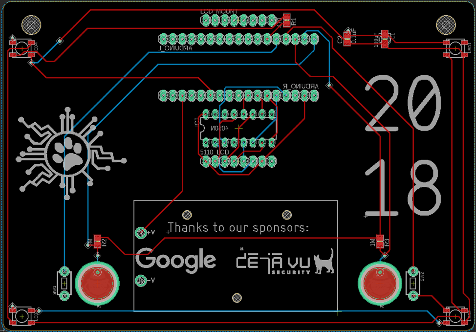
After prototyping came the fun part–designing the PCB and routing the traces. There’s a few important lessons I learned here. First, the autorouter stinks. I recommend routing the traces by hand; it's more fun and produces nicer PCBs. Second, know your printing service. Make sure your traces aren’t too small or too close together to get printed correctly. Third, remember that things like ICs, screens, and Arduinos have actual, physical mass and you must take this into consideration when placing them. Now some of you may have noticed that most of my ground pins aren’t connected to anything. This brings us to the fourth lesson: Use a ground pour/ground plane. This effectively means you make one of your PCB layers solid ground with traces channeled out of it (not seen above since it would make the entire diagram hard to read, but the entire blue layer was my ground plane). Since about half of your traces will connect to ground, this is a good way of reducing complexity. After adding just a single ground plane, I eliminated nearly all vias. Most popular PCB design software knows how to handle ground pours correctly. Fifth, don’t forget about your silkscreen, lanyard holes, and battery holders. All of these will affect component placement and trace routing. For battery holders, make sure the leads on your footprint and actual holder line up correctly, or you’re going to have a (not-so) fun time fixing it later with jumper wires.
Soldering

Soldering the badges was pretty straightforward. SMT/SMD components aren’t too bad if you have a magnifying glass and a pair of good tweezers. I recommend first dabbing some solder onto one pad, heating it up and attaching one side, then doing the other side(s), and finally going back to fix up the first side last so the component stays in place–much simpler than trying to do everything at once, plus it requires only two hands. I also recommend a healthy dose of flux. One thing to be careful of, especially if you’re new to soldering, is the order in which you solder on overlapping components. Soldering an 0805 SMT resistor through a 1cm gap between your screen (which you already soldered on) and your PCB is really not as fun as it sounds.
As a corollary to soldering, you may also find yourself needing to desolder a mistake. The fewer pins said mistake has, the easier this will be. Resistors and LEDs are fairly simple while an 8-pin Nokia LCD is downright miserable and a dead Arduino is not worth trying to remove. However, when desoldering becomes a reality, my personal recommendation is lots of solder wick, heat, and patience. If you don’t care about destroying the component you’re removing, and can do so safely without damaging the PCB or other parts, I would highly recommend taking advantage of this. The basic idea is to reheat the solder and get it to bind to the solder wick instead of the joint. You’ll have to do this several times, slowly reducing the amount of solder in the joint until you can pull it apart. If you have multiple pins, this becomes exponentially less fun. Some fun is regained if you can cut the pins off and desolder them one by one (you can even do this without any wick). The best way to handle desoldering, however, is to prevent it. Test everything before you solder it on and be careful with your heat. You don’t need to be paranoid–a few seconds at high heat is totally fine, and you can solder on an entire Arduino without pausing–just don’t hold your iron against your microcontroller for half a minute.
Conclusion

Overall, the process of creating a badge and organizing an event was a new and exciting experience. We definitely intend to continue and expand on the event in the future, including designing a more sophisticated badge while bringing down costs. Of course, organizing an event is a complicated task, and I was only one of the many people who contributed to CubCon’s success. To conclude, I’d like to thank everyone involved:
Kim, Tariq, and Kevin–our awesome organizers who worked hard over the last 3+ months to plan and prepare for the event.
Alex and Joe, our helpful staff who helped prepare the party, mix mocktails and keep everything running smoothly when the rest of us were running around frantically trying to fix issues and keep on top of everything.
Yan, Jayson, Adam, and Noid, our awesome speakers, who are the main reason anyone showed up.
Google and Deja Vu Security, who generously sponsored us so we could afford to put this event on in the first place.
M and Arclight, who answered my endless stream of questions about how electricity, circuits, and PCBs work–even the ones I really should have just Googled on my own.
OSHPark, who went above and beyond at every step in making sure our PCBs got printed in time and on budget.
Access Event Solutions, who printed our participant badges exactly to our specifications, even if our specifications may have been somewhat unusual.
Almus, Seric, and Ilya, for running the Challenge Party at DEF CON every year, that party being the main inspiration for CubCon.
The Magnificent 7–a group of eight attendees (it’s 0-based indexing), most of whom didn’t know each other before, who met up at CubCon and proceeded to solve my badge challenge with impressive speed and determination. You can read their writeup on the badge challenge here. They embody the spirit of everything we hoped CubCon would accomplish.
Finally, thanks to everyone who came to CubCon and put up with, as one observer put it, “Atlanta-in-summer conditions,” in order to participate in our event. We’ll definitely have better airflow/AC next year!